Problem/Limitations: Create a windlass/device that spans a 12cm gap with a crankshaft (not over the well/hole) that lifts a 1liter bottle at least 10 cm above the opening of the well. Material limitations: no more than 500cm^2 total area of 3/16'' Delrin sheet, 120 cm of string, and a 50cm piece of Delrin rod.
Partner (part-time): Fiona Chung
Day 1-2:
Step 1: Brainstorming (~20 minutes)


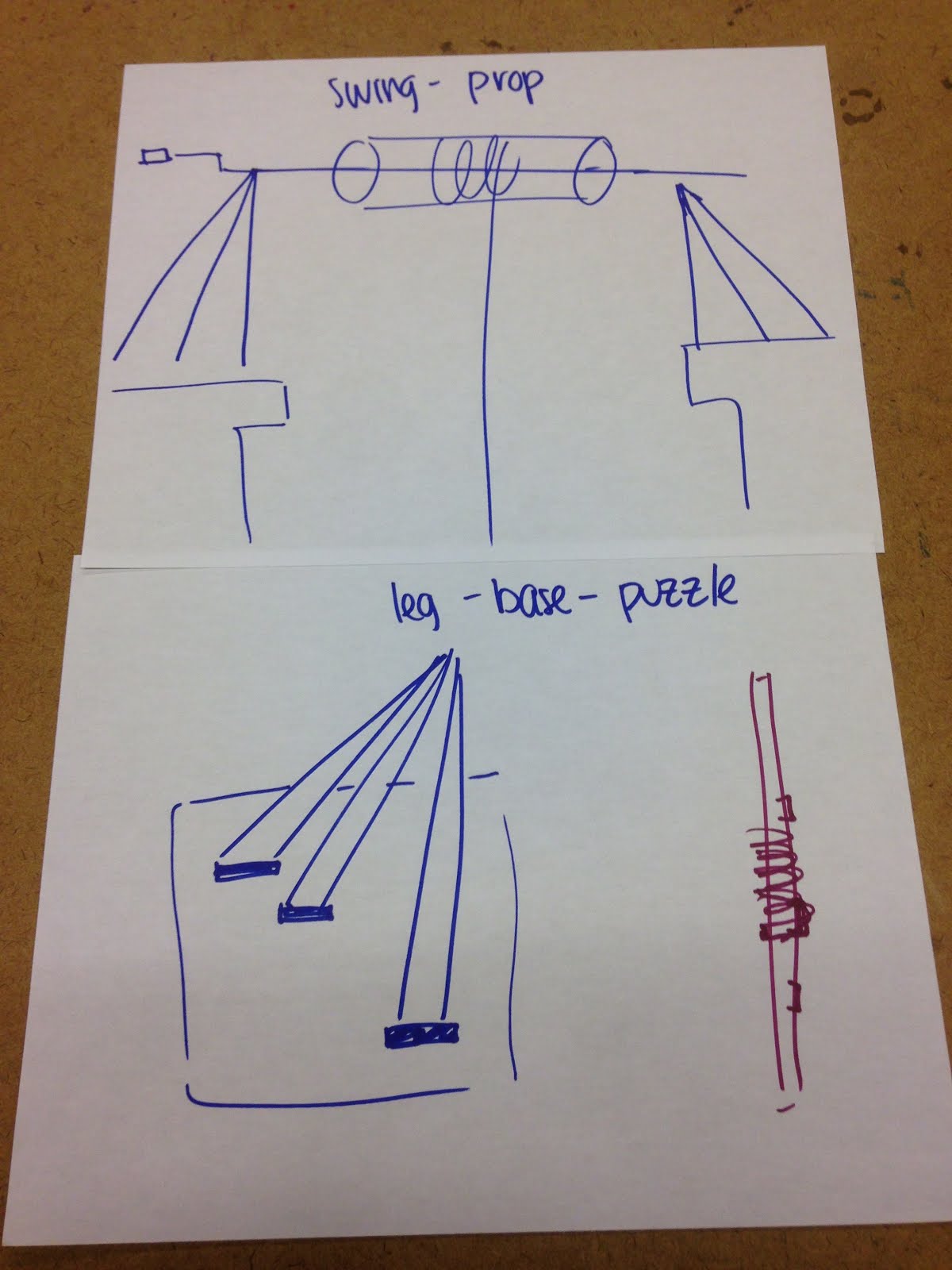

We decided that we would work on two foam-board prototypes and decide which one was stronger to model in SolidWorks:
Idea 1:
Plan: The small wheel on the side turns at a 1:1 ratio with the larger inner circles. The pencils form a triangular pyramid shape inside (hopefully exploiting the strength of triangles!) The elevated side platforms elevate so the bottle can be raised the minimum 10 centimeters above the table.
- the supports for the side platforms are very strong, but hard to model in Solidworks b/e fit at an angle
- perhaps this model is too area-costly
 Idea 2:
Plan: The triangular supports on the outside hold the center bar at least 10cm above the top of the table. The inner triangular pyramid maximizes the rate at which the bottle can be pulled up with each crank (one rotation) of the rod.
- concerns -
- the weight directly in the center will be too much for
the rod
- reduce the length of the beam that takes the
weight of the bottle
- start with the string wound around all three bars
already
- the weight will collapse the side beams in towards
center
- solution: add a center beam on top of the side
isosceles triangles
- make base of isosceles triangles larger so more
stable
Final foam-core mock-up:

Day 3:
Modeling of small holes before laser cut large parts. (this took a TON of adjustment and time, even after using the calipers the process of 3D modeling - drawing - laser cutting - testing - adjusting (repeat until fits just right) took lots of patience because the dimensions in SolidWorks are not the exact ones that will be printed in the laser cutter (due to vaporization and reduction of beam strength as the distance of the beam increases))

Part name: Square Donut (beam hole)
1st iteration: inner hole - too small
2nd: inner hole - too big
3rd: inner hole - just right (WAHOOO!)
final dimensions:
inner circle (SolidWorks): 6.2mm
outer edge: 1cmx1cm
 Part name: Bushing
1st iteration: inner hole - too small
2nd iteration: inner hole just right, increased the outer diameter
final dimensions:
inner circle: 6.2mm
outer circle: 1.5cm


Part name: Triangle Foot
1st iteration: both rectangle cutouts (slots that fit into each other) were too small
2nd iteration: just riiiiight
final dimensions:
inner rectangle: 0.508cm x 1cm
base of triangle: 5cm

Part name: T-shape and Donut Hole
1st iteration: too big
2nd iteration: still too big, but remained that way since we realized we did not need a tight fit
final dimensions:
peg: 0.9204cm x 1cm x 3/16 in (delrin sheet thickness)
All together now! One happy family!

Day 4-6: More Modeling in SolidWorks (partner dropped the class, #ridingsolo)
Problems: There was always long line for the laser cutter since cutting out shapes in Delrin takes multiple cuts and the heat from cutting out larger pieces often warps the sheet of plastic so much that other shapes to be cut out are not as precise as we hope. This resulted in an extended first prototype stage despite spending many hours in the engineering lab.


Additional problems: Default units being used SolidWorks are different from the laser cutter -- make sure they are the right dimensions before print.
Prototype 1:

Problem: The bushings on the sides were not enough (unattached) to increase the contact area that the center rotating triangular drum had with Delrin rod so under the force of the 1L water bottle, did not turn at a 1-to-1 ratio with the rod.
Plan of Action: Drill holes in the bushings perpendicular AND parallel to the rod and stick piano wire through them to increase the grip (and likelihood that the whole triangular piece will turn with the rod). Also, create a piece to attach to turn the rod.


So. After about 3 hours of drilling holes for, cutting, and hammering piano wire into my rod, it still didn't work. The bushings were too small. The holes in the rod were irreversible. It was at this point I was at t-minues 2 days til we were scheduled to present our windlasses and I was #freakinout. Like wigging out, panicked, gonna fail this project. How can I modify this iteration that it works without using too much more Delrin (I was already close to the limit)?! Thankfully, Katrina and Xi Xi were able to help me troubleshoot and unpaint me out of the corner I was in. Wooo go teamwork!
New Plan of Action: Remove the piano wire from the outside bushing and create a larger replacement bushing that (via piano wire) attaches to the Delrin rod and to the triangular apparatus. But where are we going to get the material to create the larger bushings? Cut them out of the body of the Cracked Flask! (I wasn't about to waste more delrin cutting out the new model, just imagine the side pieces have a 4cm hole in the center of each)
Note: There were a couple of problems with drilling the holes for the piano wire just by the nature of the drill press, but I managed through it.
Prototype 2: ft. hilarious photos of not-so-happy visiting student from China


Note: Start with the string wrapped around all three rods so that the force of the water bottle is never on just one rod.
Accounting:

**triangle feet are 2.71cm x 5cm (cutoff in photo)
Cracked Flask(s): about 301.5 cm^2
Triangular Piece(s): about 104.5 cm^2
Center beam: about 56 cm^2
Triangle feet: 27 cm^2
Small bushing: 1.87 pi cm^2 => 5.86 cm^2 x4 bushings => about 23.4 cm
Large bushing: 22.6 pi cm^2 x2 bushings => 77.3 cm^2
Total: 589.7 cm^2 (less if we had cut the large and small bushings out of the cracked flask piece or center support)
Reflection:
The design process was long and frustrating (perhaps would have been less so without the deadline, but when does that ever happen?). It is easy, at times, to feel like you have no idea what you are doing, and not many ideas about where to turn to next. This is where I learned about the importance of working in a team. I found it was very easy to get into my head and get lost in such a difficult (but not impossible) task, and that is when you need your partner the most. When in doubt, ask for help. Ideas, regardless of whether you end up using them, will help you out of the rut and single POV mindset.
I was surprised that our bottom triangular feet were able to make our structure so stable. The top beam, although not fastened/attached, kept the sides from caving in. The key to the stability in this structure was keeping all pieces at right angles to each other. This included putting bushings on the rod on the inside and outside of where the rod attached to the cracked flask.
One idea I saw that other teams did was create their own rectangular delrin rod to use as the center beam -- this allowed for greater friction (just by the shape) so they did not have to deal with the slippage problem I did. Pretty smart, huh? Just considering the delrin rod as the main beam, we could only control the length of the beam, however, creating the rectangular delrin rod allowed them to control a lot more of the variables that go into beam bending (think cantilevers), despite using the same material.
Time-wise I think that I might try to get a first prototype out a lot earlier, since it took a lot of time to trouble shoot small/big problems from there. However, dealing with the foam model is also really great for dealing with main structural flaws so you can create a feasibly successful model. Overall, this entire project took about 25 hours and I wouldn't have spent much of that time differently because the steps I went through were each necessary in getting to the finished product I have today. That being said, if I was given more time, I would have adjusted the handle on the side so it was easier to turn (simple 30 minute fix), and made the triangle pieces smaller so that the twisting force on them was smaller.
Skills:
- brainstorming
- trouble-shooting (teamwork necessary)
- 3D modelling in SolidWorks
- fastening & attaching

Your windlass is so cool. I love how it's nearly all triangles. Using triangular feet instead of a rectangular platform to hold the base was genius. The name of your windlass is also pretty awesome.
ReplyDelete<3 thanks!!
DeleteI love how organized your blog post is. I especially love all of the pictures because they make your thought process easy to follow. Your windlass design is also very creative.
ReplyDeleteThanks!!!
Delete