Friday, April 29, 2016

Final Project Week 4

Partner: (the ahhhmazing) Katrina Montales

This week we worked on fixing the belts. The space between the lego chains would change as the belt went around the gear. So we tried attaching smaller pieces of velcro. However, just having one velcro piece attached at the bottom did not provide enough support for moving the marble holders. As an alternative solution, we found some Under Armor headbands. They kept slipping off of the pieces from the inside of the lego wheels, so we tried sewing them to the lego tracks (ps: sewing takes a long time, I spent about 3 hours sewing...). In addition, we tried adding a second track to support the upper half of the marble holders.


Next, we worked on cutting out a Delrin piece to reduce the friction the marble holders have with the platform they sit on. This was pretty simple because of the extensive Solidworks experience I had from the windlass project. The delrin piece for the top has a hole for the marbles to be loaded into, and bottom doesn't have it.


Just like when I tackle a large problem in computer science, break it down into small sub-problems. First I set up the basic circuit to work with the button and the LED. I wrote code so that when the button was pressed, the LED would light up.


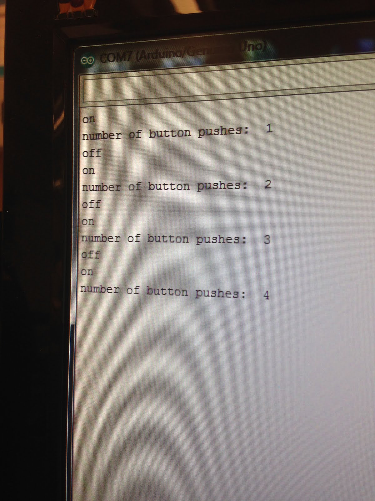
Next, I found code online that would count the number of times the button has been pressed (basically by maintaining a variable that we can compare the current state of the button to to see if the state has changed). The result is shown in the serial, a little something like this:


Putting it all together:
I inserted the working parts into our code for the normal functioning of the marble releaser (behavior determined by the reading on the light sensor). We have two buttons each using very similar code and a while loop. For the fast-forward button, I set to run while the number of button pushes is above 0, run the code for releasing one marble, and then decrement the button pushes counter. For the delay button, practically the same code except that we set the motors to speed of 0, and then delay for a single marbles units of time.

Lastly, we worked on fine tuning all of the separate parts so that they work well together (thinks like tweaking the light sensor). In addition, at our meeting with our client, Becky, at the child studies center, she mentioned that our entire contraption was a bit distracting, so we constructed a main board for the children to look at (and only see the tubes and marbles). Here is a video of our contraption working for the most part (we just need to tweak how much motor two rotates to load in the new marbles, right now it is a bit too much, and finalize the attachment of the funnel.) Wish us the best of luck on our presentation!


Friday, April 22, 2016

Final Project Week 3 (Iterate, iterate, iterWAIT-- IT WORKS!)

Partner: Katrina Montales

This week we worked on prototyping (lots and lots of iteration).

The first problem we tackled was creating the mechanism to release only one marble! After many iterations, we found a lego piece that could be attached to the track to separate the marbles. However, we could only find 10 and ordering the T pieces would take some time (and money!) so we decided to work with what we got. With the limitation of 10 T-pieces, we needed to create a track that was short enough to only use ten, but large enough to fit around the gears used to turn the track. We tried 8 and 24-toothed gears and had the most success with the 24toothed gears. In addition, we had to find the optimal amount of space between the T-pieces that was also compatible with the separation in the gears(so the chain didn't go slack in the middle). The ideal distance was to have one chain link between each T piece, however this loop did not work well with the gears, so we went with two chains between each T piece. In order to only release one marble at a time, we set a top bar that would push any marbles above the bottom one (to be released) into the next holder in the chain. Note, this works almost 100% of the time. Since the grey T pieces are removable, they also rotate, so if we were to place very heavy marbles or more than 15 marbles to be all loaded simultaneously, the T pieces may rotate and release more than one marble at a time.
initial prototypes (not all documented)
the top bar (red) prevents multiple marbles from being released at once

Top view (where marbles will be loaded)
The next material we dealt with was the rigid clear tube! Using a ruler, we divided our 6 foot tube into 10, 6 inch long pieces. Using a power-saw we cut the tube. The first one was a little bit shorter than we wanted it to be (difficulty maneuvering the 6 foot tube), but practice makes perfect and by the end, we were cutting spot on! In the end, we were left with 10 tubes, 5 for each activity during the day, and 5 for recollecting the marbles to be reset at the end of the day.


Next, we experimented with various different structures for holding and releasing the marble. One of the ideas I experimented with was pieces of lego that stuck out, reducing the force of all of the marbles directly on the rotating track.

In the end, we had a structure similar to that of a tube that allowed the marbles to stack up. But the lego pieces in front and back prevents more than one marble from being released at a time.


Another problem we ran into was that the Arduino and Bricktonics Shield only had two ports for motors, so we had to brainstorm a way to have the top and bottom rotating mechanisms for the marble tubes powered by the same motor. (see solution in the video)


Next, we worked on the arduino code for turning the motors. Let motor 1 be the one powering the releasing mechanism and motor 2 be the one powering the rotating track (that holds the tubes of marbles). In english, the code says: when the light sensor senses there are marbles there, then rotate motor 1. If the light value is higher (meaning no marbles are sensed), then rotate motor 2.

One of the (many) problems we ran into was the that there were still marbles that needed to be released after the light sensor had sensed that there was no more marbles, so we set the code to: after it senses the higher light value, then rotate motor 1 six times (the number of undetected marbles) before rotating motor 2.

Another problem we came across was that there was a difference in the light value that was sensed when there was nothing above the marble tube and when there was the empty tube, so we had to adjust the code to account for that, but still now it is a bit finnicky about when it wants to turn.


In the video: you will see the light sensor sensing no marbles above it, so motor1 turns six times before rotating the bottom and top platform. 

Lastly, we spent a (surprisingly) long time trying to attach the velcro to the track for the marble tubes. This was because the spaces between the chain (when the chain is in contract with the gear) is larger than when the chain is not in contact with the gear. Thus, we found out the hard way that gluing (with a hot glue gun) just one long piece of velcro around the track was not going to work. After multiple iterations, we found success in gluing separate small pieces of velcro to the track. 


A final(ish) video of our semi-working prototype (we found that we needed paper over the legos to smooth and reduce the friction of the bottom of the tubes against them.) The first time we tested this all together, the marble tube that was releasing the marbles (hypothetically) shifted over, but got caught on the ledge. Since the gear chain was held tightly around the gears, it snapped and both the chain and attached tubes fell off (and into my lap!), so in the video, I am holding a paper band around the tubes in hopes of keeping them more balanced for the sake of testing. 


Reflection: Overall, the design process (note: we aren't done yet!) has been long and full of bumps, however it really is fun to try and solve new ways around these problems. A lot of engineering has been working at building something until it works. Sometimes it is easier to step away from a problem for a little bit (let it stew in your mind) and then come back at it from a fresh angle. Katrina and I spent about 14 hours in the engineering lab hacking at this project and I am glad it is starting to shape up. Notes for improvement for next time, we need to implement two buttons each with very similar functions 1) press the button how many marbles you want to delay 2) press the button how many times you wish to fast forward. In addition, we know that the marble tube structure isn't all too stable, so we were thinking that raising the rotating mechanism to attach to the middle of the tube might be a more effective way to keep the structure balanced and functioning. 


Friday, April 15, 2016

Final Project Week 2

Partner: Katrina Montales

This week we finalized our order plans and worked on a mockup of our first prototype.

Material Order Plans:
  • We already have all the legos that we could need (stored in the lego cabinet)
  • weight sensor --> color sensor --> light sensor
    • The weight sensor was phased out of our plan, we decided we no longer needed to sense the weight of the marble, but have it release a marble on the set time interval.
    • The color sensor was prohibitively expensive ($40 of our $50 budget) Although Amy offered to buy it outside of our budget because she could use a color sensor in later classes, we found a way around our problem. Necessity breeds innovation, right?
    • We are trying to see if, just based on the sensitivity of the light sensor, figure out when the compartmentalized marble holder needs to be shifted over
  • We want a clear pipe to hold the marbles so we can see the various colors that correspond to the duration of different activities. The diameter of the marbles is approx. 9/16'' so we need a tube that has an inner diamater between 10/16'' and 1''.
  • 3 total motors + Arduino + Bricktonix shield for controlling the motors and feedback from the light sensor
  • Lastly, we need various colored marbles (to represent time)! 

Initially, we tried to minimize the number of motors needed to power the shifting mechanism. However, this would not have been possible with the way that the marbles fill the second container (orange).


So we created a model that has two motors shifting the marble containers, pushing them in opposite directions!


The second problem we tackled was using a light sensor. We needed to find a way to have the light sensor sense if there are were marbles left in the tube, or if it should shift to load in the next activity's marbles. 
Ideally, we would be able to have a light sensor right underneath the stack of marbles that could point upwards and sense if there were any remaining marbles that needed to be released. However, given the size and shape of the light sensor, this was not an option.


So we devised a plan to have the light sensor be shifted off center. With this plan, we would have to build up some legos on top off the face of the sensor so to protect it from marbles falling directly on the sensor. The idea behind this plan is that when all of the marbles of a specific color run out, then the light sensor will sense a high light value and shift the marble container over and release the next activity's marbles.


Alternate plan:
Attach the light sensor to a point behind the releasing mechanism so that when the light sensor senses that there is no marble there, then it will shift over the marble container (and also the bottom marble container).  If this doesn't work, we discussed using an ultrasonic sensor to sense the distance to the nearest object for marble detection. All trial an error, but hard to do without actual marbles!

In addition brown platform underneath the top container is fixed, functioning as the bottom of the marble container. However the marble container itself does not have a bottom, so that it can be shifted over, releasing the marbles simply through the use of gravity.


Also, I wrote out some pseudo-code for planning out how we should approach each part of our project. I find that it is much easier to take apart the problem in english, and then translate that into code rather than trying to balance it all in my head at once.

Thanks for reading! I'll update you again in a within week!

Thursday, April 14, 2016

MATLAB: So take of all your clothes~ (thermal systems part 2)

Partner: Katrina Montales

In this activity, we worked with an actual thermal system composed of the following parts:
  • heater - a 50 ohm resister powered by 18 V supply (we can control adjust the power) that converts electrical energy into thermal energy
  • thermal reservoir - the resister is inside a brass casing with good thermal conductivity (note: do not touch)
  • temperature sensor (thermistor) - has contact with the thermal reservoir, it is wired into a 10 kilo-ohm resistor, creating a "voltage divider circuit"
Baseline information about our specific thermal system (given):

Task 1: run the script test_thermal.m that runs for 300 seconds at 100% power (6.5 Watts) and calculate the unknown physical parameters Rth and C

test_serial code:

test_thermal code:

Resultant graph (note the little blips in the first run were due to disturbance in the environment (someone moving the thermal reservoir, changing the measured temperature)):
let the thermal reservoir cool down and ran the program again, no blips!


Calculate Rth and C:
(for a refresher on these equations, see MATLAB: It's getting hot in here~ (thermal systems part 1))
Gut check your work:


The time constant is about 138 seconds.

The graph shows that y(300) = 378K and y(1) = 315K. Thus the time constant is the x value that corresponds to the y-value of (378K-315K)*(63.2%) = 39.82. Using a ruler, we determined that the value of time with a temperature change of 39.82 degrees is about 130 seconds, which is close to the calculated time constant value of 137.74 seconds.

In laypeople terms, we predict the heater will heat up 63.2% in 130 seconds, which is close to what the experimental data showed for 137 seconds. Not bad!

Task 2: Run Matlab simulation of the heatsim.m (using the Rth, C, and P that we calculated):

heatsim.m code:


(heatsim vs actual)


Ignoring the difference in scaling, the differences between the experiment and simulation were not that different. The simulation predicts that the heater could heat up at a rate much faster than in reality (perhaps due to environmental factors or delays). 

Task 3: Bang-bang Control -- modify test_thermal.m to change the power based on whether the measured temperature is above or below the target temperature (340K)

Bang-Bang experiment failed code (we never turned the heater back on):


Our failed bang-bang experiment:


Success!


Bang-bang simulation code:


Overall, the differences between the experiment and simulation are not all too large. There are more dramatized differences in the temperature changes when the experiment has the heater on and off, but this is probably because there are more delays between the actual temperature of the heater and the time that the sensor senses the temperature and adjusts the power. All in all, pretty closely well replicated results!


Task 4: Proportional Control
-review on proportional control-
error = target state - present state
set power = Kp * (target temp - T) when Kp is the proportional gain coefficient

Code for Simulation:


Code for Experiment:


Kp = 0.02, Simulation(top) and Experimental (bottom)


The simulation shows a very minor increase in temperature while the experiment shows even less or no change in temperature over the 300 seconds. What we can see in both the simulation and the experiment is that a proportional gain coefficient of 0.02 is far too little power to create significant temperature change, thus we never reach the control set point.


Kp = 0.2, Simulation(top) and Experimental (bottom)


The simulation shows a more gradual but constant increase in temperature from t=0 to t=50 while the experiment shows that the heater takes a little while to "heat up". In other words, there seems to be a small delay in the temperature increase in the experiment because the power takes a little bit of a buffer time to create an actual change in temperature. In both the simulation and experiment, we do not achieve the target temperature because the power (theoretical and actual) being supplied to the heater is still too small.


Kp = 0.5, Simulation(left) and Experimental (right)

The simulation shows a very steep initial change in temperature in the first 50 seconds. In the experiment, we also see a very steep initial increase in temperature, but it is delayed a little bit, as seen in the previous experiment as the heater takes some time to heat up. In addition the slope of the rate of increase in temperature for the experiment is not as steep as that of the simulation because the experimental data is limited by reality. In reality, we are limited to 6.5 Watts of power. However, even if we put in an infinite amount of power (aside from all dangerous and actual problems with that), there would still be a limit to how fast the heater could heat up, making the slope of the temperature increase less steep than that of the simulation.


When the gain is too small (0.05), the experimental results do not show a significant temperature change. If the gain is too high, the system behaves very similar to that of a bang-bang controller, since the thermal system is basically at full power until the target temperature is achieved, rendering the temperature graph for the first 50 seconds practically linear. (more power is not always better!) Thus, the ideal gain is somewhere between 0.2 and 0.5 so that we can reach the target temperature, but still more efficiently use the power.

Reflection:
In this assignment, we were able to see how the simulations and actual experimental results were similar and different. Although they are often very similar, there are a couple of differences due to limitations of reality -- such as delays and power limits. In addition, this was a great way to practice coding for bang-bang and proportional control because we were able to see the actual experimental results of code that was not correct. Thermal systems are not only interesting, but also important to the final projects tackling the problem of temperature regulation for people who can no longer do so. Just as in this assignment's experiments, there are limitations to how hot and how fast you can heat up someone while keeping everything safe. Just 100 years ago, houses were smaller because they could much more efficiently be heated and maintained at the ideal temperature because there was less air to heat-up and maintain. Thanks to modern technology and the implementation of ventilation systems, we have a bit more control over heating and temperature regulation, but we still have far to go! If you want to read more about modern air temperature regulation and heating in thermal systems, check out the nest -- the smart way to heat/cool your home that fluctuates as people are in or not in the home.

Animals have complex heat regulation systems too!