Sunday, February 28, 2016

Lego Racer J&M Take 2nd Place

Problem: Design a Lego car using the "old motor" (high speed, low torque) to move a 1 kg weight 4 meters across the finish line (and win the race!).

Partner: Marissa Okoli


First, we started by brainstorming possible variables that would affect the performance of our car:
  1. speed-to-torque ratio
  2. which size wheel to use
  3. how many wheels to use
  4. where the weight should sit in the car (front/back)
  5. how the weight should sit in the car (standing up or lying down)
  6. where should the motor me powering the wheels (from the front or back)
  7. where to put the motor and the pico-cricket and still maintain a balanced car
Process: Mainly Composed of TONS of Trial and Error (fail fast and early, iterate as needed)

Trial 1:

After holding the 1kg weight in our hand, we thought we were gonna need a LOT of power, so we started with a huge gear ratio in an attempt to guarantee that we would be able to move the weight.


Gear Chain Ratio: 1/495

Conclusion: Way too slow, not so much power needed


Trial 2:

...Let's try something of the opposite extreme, a very very low gear ratio and just see if the car will move.

Gear Chain Ratio: 1/3

Reflecting now, I see that the big 40-toothed gear in the center was effectively useless, aside from the fact that it was adding friction. Regardless, I was learning about gear ratios.

Conclusion: Not nearly enough torque to move the weight.


Trial 3:

For the next iteration, I came and worked on a Saturday, so I assume that is what can be attributed to the major brain fartage here. As I was still new to working with gears, I added a lot of unnecessary gears. Although there are a ton of gears in this car, the gear ratio ended up being relatively low due to the way I arranged the gears.

Gear Chain Ratio: 1/45

Racing time: 24 seconds

Conclusion: At the time, I thought that the gear ratio here was 1/225, so we thought the gear ratio could still come down a bit. Other problems: the structure of the car is weak and the motor is not securely attached to the car. Also, needed to work on building a place for the weight to sit.

Other hilarious video of an attempt to test the car -- the weight was concentrated on the back, also where the wheels were being powered. The car was unbalanced and the weight was unsecured aka failure an an attempt to even move the car.


Trial 4:

Trying a lower gear ratio than (what we thought was) 1/225. At this point, I understand that trying these, in actuality, higher gear ratios is futile and not moving us towards the goal. Nevertheless, they were actual trials and part of the process of learning about how gear chains work.

Gear Chain Ratio: 1/125

Racing time: 40+ seconds

Iteration notes: lower the gear ratio even more (also, start keeping a more accurate chart of what you have tested and the times so you can problem solve a lot easier)


Trial 5: (wheel testing)

Short & Fat wheels: 50 seconds

Big & Skinny wheels: 32 seconds

It was at this point that we had decided that three wheels were what we needed for stability and weight distribution. Also the use of the large wheels, since they were directly hooked up to the gear chain turned at a 1-to-1 ratio with the final gear in the chain, so a larger wheel meant a greater circumference and a coverage of more ground with each turn of the wheel. #need4speed

Trial 6:   +Fail vid

Gear Ratio: 1/25

Racing time: 15 seconds

*gasp* It works at 1/25!! Now all we need to do is keep testing lower gear ratios until we have hit the lowest one that still moves the weight! The weight at the front of the car helps counter the 1kg weight.


Trial 7:

Gear Ratio: 1/15

Racing time: < 11 seconds

Iteration notes: After some online research, we found that laying the weight down flat would lower the center of gravity. In addition, we wanted to keep the weight centered and near the motor to optimize for speed.

Note: The car is a little bit lop-sided but with a bit of adjustment of the placement of the weight and the wheels, it is easily fixed.

Trial 8: How low can you go?

Gear Ratio: 1/10

Racing time: 13 seconds

Note: The 24-toothed gear was added in to have enough spacing to have the main axel and wheels fit together well, but at the cost of added friction.

Iteration notes: This gear ratio was so low that the car needed bit of a push to get started (overcome the static friction), but was able to make its way. However, we decided that this was not a better option than the clearly sufficient 1/15 gear ratio. Ladies and gentlemen, we have a wwwiiinnnneeerrrr! (hint: its not trial 8)


Trial 9: Final Product


Gear Ratio: 1/15

Racing time(on actual race day): 9.35 seconds

Note: the car tends to go to the left a bit, this was fixed just before the race through an adjustment in the wheel alignment


Reflection:

The process was long, but definitely worth-while in the end. This project was definitely different than the previous ones because all of the parts were pre-made, all we had to do was figure out how to fit them together in the best way. With each of the initial mistake I made in calculating the gear ratio, I quickly learned the correct way and made lots of progress towards a faster and better lego racer. I also learned how to set up a clear chart for keeping track of what we had tested and taking note of the numeric time that each lego racer took to cross the finish line (really a great idea for tracking progress and optimization). Overall, I spent about 15 hours on this project and I would not have spent the time much differently. Each iteration taught me valuable intuition and knowledge on the gear chain process and optimization. Now you tell me, which video did you like the most?

Skills/Motos:

  • iterate, iterate, iterate
  • fail fast and early
  • keep meticulous notes (or videos) to help keep track and make progress with future iterations
  • building strong/sturdy structures with legos
  • adjusting gear chains
  • working with bushings
  • working with pico-cricket


Sunday, February 21, 2016

Windlass: The Birth of the Cracked Flask


Problem/Limitations: Create a windlass/device that spans a 12cm gap with a crankshaft (not over the well/hole) that lifts a 1liter bottle at least 10 cm above the opening of the well. Material limitations: no more than 500cm^2 total area of 3/16'' Delrin sheet, 120 cm of string, and a 50cm piece of Delrin rod.

Partner (part-time): Fiona Chung

Day 1-2:
Step 1: Brainstorming (~20 minutes)


We decided that we would work on two foam-board prototypes and decide which one was stronger to model in SolidWorks:

Idea 1:
Plan: The small wheel on the side turns at a 1:1 ratio with the larger inner circles. The pencils form a triangular pyramid shape inside (hopefully exploiting the strength of triangles!) The elevated side platforms elevate so the bottle can be raised the minimum 10 centimeters above the table.

- the supports for the side platforms are very strong, but hard to model in Solidworks b/e fit at an angle
- perhaps this model is too area-costly


Idea 2:
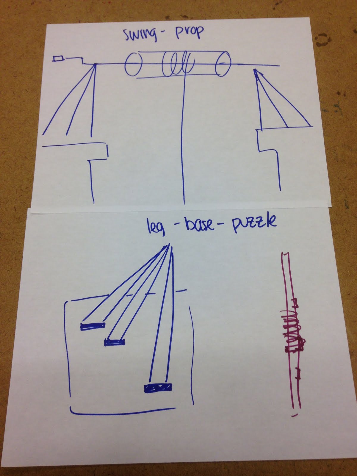
Plan: The triangular supports on the outside hold the center bar at least 10cm above the top of the table. The inner triangular pyramid maximizes the rate at which the bottle can be pulled up with each crank (one rotation) of the rod.

- concerns -
   - the weight directly in the center will be too much for
   the rod
      - reduce the length of the beam that takes the
      weight of the bottle
      - start with the string wound around all three bars
      already
   - the weight will collapse the side beams in towards
   center
      - solution: add a center beam on top of the side
      isosceles triangles
      - make base of isosceles triangles larger so more
                                                                       stable


Final foam-core mock-up:


Day 3:
Modeling of small holes before laser cut large parts. (this took a TON of adjustment and time, even after using the calipers the process of 3D modeling - drawing - laser cutting - testing - adjusting (repeat until fits just right) took lots of patience because the dimensions in SolidWorks are not the exact ones that will be printed in the laser cutter (due to vaporization and reduction of beam strength as the distance of the beam increases))


Part name: Square Donut (beam hole)

1st iteration: inner hole - too small
2nd: inner hole - too big
3rd: inner hole - just right (WAHOOO!)

final dimensions:

inner circle (SolidWorks): 6.2mm
outer edge: 1cmx1cm


Part name: Bushing

1st iteration: inner hole - too small
2nd iteration: inner hole just right, increased the outer diameter

final dimensions:

inner circle: 6.2mm
outer circle: 1.5cm


Part name: Triangle Foot

1st iteration: both rectangle cutouts (slots that fit into each other) were too small
2nd iteration: just riiiiight

final dimensions:

inner rectangle: 0.508cm x 1cm
base of triangle: 5cm


Part name: T-shape and Donut Hole

1st iteration: too big
2nd iteration: still too big, but remained that way since we realized we did not need a tight fit

final dimensions:

inner rectangle: 0.55cm x 1.1cm
peg: 0.9204cm x 1cm x 3/16 in (delrin sheet thickness)


All together now! One happy family!


Day 4-6: More Modeling in SolidWorks (partner dropped the class, #ridingsolo)

Problems: There was always long line for the laser cutter since cutting out shapes in Delrin takes multiple cuts and the heat from cutting out larger pieces often warps the sheet of plastic so much that other shapes to be cut out are not as precise as we hope. This resulted in an extended first prototype stage despite spending many hours in the engineering lab.

Additional problems: Default units being used SolidWorks are different from the laser cutter -- make sure they are the right dimensions before print.

Prototype 1:


Problem: The bushings on the sides were not enough (unattached) to increase the contact area that the center rotating triangular drum had with Delrin rod so under the force of the 1L water bottle, did not turn at a 1-to-1 ratio with the rod.

Plan of Action: Drill holes in the bushings perpendicular AND parallel to the rod and stick piano wire through them to increase the grip (and likelihood that the whole triangular piece will turn with the rod). Also, create a piece to attach to turn the rod.


So. After about 3 hours of drilling holes for, cutting, and hammering piano wire into my rod, it still didn't work. The bushings were too small. The holes in the rod were irreversible. It was at this point I was at t-minues 2 days til we were scheduled to present our windlasses and I was #freakinout. Like wigging out, panicked, gonna fail this project. How can I modify this iteration that it works without using too much more Delrin (I was already close to the limit)?! Thankfully, Katrina and Xi Xi were able to help me troubleshoot and unpaint me out of the corner I was in. Wooo go teamwork!

New Plan of Action: Remove the piano wire from the outside bushing and create a larger replacement bushing that (via piano wire) attaches to the Delrin rod and to the triangular apparatus. But where are we going to get the material to create the larger bushings? Cut them out of the body of the Cracked Flask! (I wasn't about to waste more delrin cutting out the new model, just imagine the side pieces have a 4cm hole in the center of each)

Note: There were a couple of problems with drilling the holes for the piano wire just by the nature of the drill press, but I managed through it.

Prototype 2:  ft. hilarious photos of not-so-happy visiting student from China

Note: Start with the string wrapped around all three rods so that the force of the water bottle is never on just one rod.

Accounting:

**triangle feet are 2.71cm x 5cm (cutoff in photo)

Cracked Flask(s): about 301.5 cm^2
Triangular Piece(s): about 104.5 cm^2
Center beam: about 56 cm^2
Triangle feet: 27 cm^2
Small bushing: 1.87 pi cm^2 => 5.86 cm^2 x4 bushings => about 23.4 cm
Large bushing: 22.6 pi cm^2 x2 bushings => 77.3 cm^2
Total: 589.7 cm^2 (less if we had cut the large and small bushings out of the cracked flask piece or center support)

Reflection:

The design process was long and frustrating (perhaps would have been less so without the deadline, but when does that ever happen?). It is easy, at times, to feel like you have no idea what you are doing, and not many ideas about where to turn to next. This is where I learned about the importance of working in a team. I found it was very easy to get into my head and get lost in such a difficult (but not impossible) task, and that is when you need your partner the most. When in doubt, ask for help. Ideas, regardless of whether you end up using them, will help you out of the rut and single POV mindset.

I was surprised that our bottom triangular feet were able to make our structure so stable. The top beam, although not fastened/attached, kept the sides from caving in. The key to the stability in this structure was keeping all pieces at right angles to each other. This included putting bushings on the rod on the inside and outside of where the rod attached to the cracked flask.

One idea I saw that other teams did was create their own rectangular delrin rod to use as the center beam -- this allowed for greater friction (just by the shape) so they did not have to deal with the slippage problem I did. Pretty smart, huh? Just considering the delrin rod as the main beam, we could only control the length of the beam, however, creating the rectangular delrin rod allowed them to control a lot more of the variables that go into beam bending (think cantilevers), despite using the same material.

Time-wise I think that I might try to get a first prototype out a lot earlier, since it took a lot of time to trouble shoot small/big problems from there. However, dealing with the foam model is also really great for dealing with main structural flaws so you can create a feasibly successful model. Overall, this entire project took about 25 hours and I wouldn't have spent much of that time differently because the steps I went through were each necessary in getting to the finished product I have today. That being said, if I was given more time, I would have adjusted the handle on the side so it was easier to turn (simple 30 minute fix), and made the triangle pieces smaller so that the twisting force on them was smaller.

Skills:

  • brainstorming
  • trouble-shooting (teamwork necessary)
  • 3D modelling in SolidWorks
  • fastening & attaching


Sunday, February 14, 2016

Mechanisms

Is it me? Or are you just e-gear-to see me? I guess wheel have to see...

Today we are reviewing a mechanism from the Schröder Collection (Foundation of Science and Technology in Florence, Italy). More specifically, the FST1356 Maltese Cross Intermittent Mechanism (also known as the Geneva Drive). This mechanism translate continuous rotational motion into intermittent motion.

As the drive wheel (red) spins, the pin slides into the driven wheel (blue). While the pin is in contact with the driven wheel, both pieces turn. Conversely, any time when the pin is not in contact with the driven wheel, the driven wheel does not turn -- thus the intermittent motion. The inner semi-circular shape holds the driven wheel in place whilst the drive wheel turns.

The Geneva Drive modifications:


I think one of the most interesting motions you can get out of simple mechanisms like this are the ones that go between continuous and discontinuous motion. For example, how might this mechanism have to be adjusted if we wanted to to use an ovular/elliptical shape rather than a symmetric circular one? How might one go about adjusting the drive wheel for a driven wheel with more than four notches? (see cheat solution here)

This mechanism could be used as a wind-ing tool, such as in clocks or other such tools. Another possible application could be in assembly-line type machinery: for example, in machines that are filling bags of candy, the motion needs to be intermittent in order for the machines to have the time to fill the bags before moving on. A much simpler example would be the rotation of frames on a film real rotating intermittently (but at a very fast rate).


Sunday, February 7, 2016

Fastening & Attaching

Partner(s): Jiaming Cui

Goal: Learn how to connect two pieces of Delrin (acetal) together using heat-staking or piano-wire. Additionally, learn about loose and tight fitted bushings on Delrin rods.

Station A (drill press, arbor press, piano-wire fastening):

  • benefits: 
    • a relatively simple way to make a hinge-type attachment of two pieces of Delrin
    • easily modified (piano wire is removable, can shave down corners to allow for more movement)
    • not time intensive
  • drawbacks:
    • you must remember to use to different size drill bits to make an effective connection
    • must use a file to adjust for more movement in the hinge (but filing down is irreversible) (another way to allow for more movement is to have the holes further away from the end, closer to the center)
    • two pieces must fit together relatively well (measurements vary with thickness of Delrin and number of times required to cut through it)
    • the hole drilled is irreversible and must be in the right place the first time (note: it may be difficult to get the wire through both holes if they are not in the same place)
  • This method of fastening is likely best to use when fastening together two pieces of Delrin into a hinge or moveable joint. In addition, this may be better for prototyping or initial models of a product because the way pieces fit together need not be as exact as say with a peg and slot.


Station B (thermal press/heat stake):

  • benefits:
    • fastest way to join two pieces of Delrin together
    • provides a strong joint between the two pieces involved
  • drawbacks:
    • permanent
    • requires the piece of Delrin sticking through the hole to be sufficient to melt and make the seal but not excessive
    • little flexibility
    • alters the shape of the pieces involved
  • This method of attaching two pieces of Delrin together is a strong and permanent, to be used at times when you want a steadfast, reliable, unmovable connection (in the foundation of a model).


Station C(Calipers, bushing measurements and tolerances, peg and slot measurements and tolerances):

  • benefits:
    • requires least material (and connection effort) to join together two pieces of Delrin
    • flexible/changeable connections between objects
  • drawbacks:
    • require high level of precision so that the two pieces fit together almost perfectly
    • non-permanent
  • This method of connecting may be preferable when you want the least permanent yet stable connection between pieces. In addition, in putting together a puzzle like structure, there is an elegance (and aesthetic aspect) in pieces that fit together almost perfectly without the use of additional material. 

Exploration of loose and tight fit bushings:


  1. Measure the outer diameter of a Delrin rod (6.35mm)
    • Inner diameter of bushing:
      • press fit: 6.25mm
      • tight fit: 6.45mm
      • snug fit: 6.56mm
      • loose fit: 6.67mm
    • Observations:
      • The bushing with an inner diameter less than the outer diameter of the Delrin rod did not fit.
      • The bushing approx. 0.1 mm greater than the Delrin rod diameter fit tightly but was not moveable.
      • The bushing approx. 0.2 mm greater than the Delin rod diameter fit snugly but still would not slide.
      • The bushing with an inner diameter > 0.3 mm than the Delrin rod diameter easily slid on and off.
    • A tight bushing may be required for when you want the rod inside to rotate to at a 1:1 ratio as the bushing outside of it, say in a car axel to turn the wheel. 
    • A loose bushing may be required on a bicycle's front wheel -- to hold a rod in place, but allow it to turn freely.
  2. Measure the relevant dimensions for the peg and slot:
    • rod: 
      • dimension: 6.35mm
      • tight fit: 6.42mm
        • difference: 0.07mm
      • loose fit: 6.67mm
        • difference: 0.33mm
    • peg 1:
      • dimension: 3.23mm
      • tight fit: 3.38mm
        • difference: 0.17mm
      • loose fit: 3.54mm
        • difference: 0.31mm
    • peg 2:
      • dimensions:6.84x4.92x4.93 mm^3
      • tight fit: 7.04x5.13x4.98 mm^3
      • difference (in each respective dimension): 0.2x0.21x0.05
    • The differences in the tight fit are lower than that of the loose fit, but that is to be expected. Loose fits tend to be about 0.3mm larger than the dimension we are measuring.
  3. Measure the thickness of the peg plate and compare to the SolidWorks dimensions:
    • Line 1:
      • SolidWorks Dimension: 0.135 in
      • Actual Dimension: 0.140 in
        • difference: 0.005 in
    • Line 2:
      • SolidWorks Dimension: -0.125 in
      • Actual Dimension: 0.133 in
        • difference: 0.008
    • Line 3:
      • SolidWorks Dimension: 0.115 in
      • Actual Dimension: 0.125 in
        • difference: 0.010 in
    • Although the differences between the SolidWorks dimensions and the actual dimensions are not very large, we have not taken into account the thickness of the peg plate and how many times it was cut in the laser cutter. Laser cutters, by nature, do not cut straight down -- meaning that the beam weakens in strength as the distance the beam has to travel increases -- so cuts in the Delrin are actually at an angle. Therefore, measurements using the Caliper tend to favor one side of the cut. Possible improvements to a laser cutter (although I do not know much about the science of it) would be to have the beam closer to the material in an attempt to lessen the impact of distance on the strength of the beam. Another possible improvement to the process is to flip the Delrin sheet after one cut and cut from the other side (this would require a flipped version of the 2D model cutout).
    • Note: perhaps using a smaller unit would have been better for this exercise, using mm rather than in. to ascertain more precise measurements.
Thanks for reading! Don't get stuck in the snow!

ps: this is my favorite gif at the moment

Bottle Opener: The Creation of HS Frowny

Problem: We want to open a non-twist off glass bottle (like the classic coke bottles) but can only cut out of a shape in 2D out of acetal using a laser cutter. Dimensional restraints: no more than 6''x6''x1/4''.

Partner(s): Scarlett Cheon

Day 1:
Step 1: Brainstorming for 5-10 minutes ~10 ideas
(working towards that 2 ideas/minute #goals)


Top 2 Design ideas, Final plan (center):

We thought we could be sneaky by combining two ideas, so in designing one prototype, we could test two different designs.

Step 2: Build a prototype out of foam core (to scale). It was at this point that we realized why making the foam core model to scale was important.

Note: This step was a struggle because we realized that attempting to cut curves with an Xacto knife is not so easy. But hey, practice makes perfect, right?

Day 2:
Step 3: Create a 3D design (and drawing) using SolidWorks 2014.
We struggled with SolidWorks because it is not exactly intuitive, but after about 3 hours of "uhhhh is that button it? try that one... WOOOO YEAH!! What step is next?" we got a working model.


Step 4: Cut out our prototype out of 3/16'' Acetal using the Laser Cutter. #exciting
This cut-out took two cuts in the laser cutter.


Step 5: Test the prototype.

We ran into a problem: since we had set the inside circle's diameter to be approximately the same as the diameter of the bottle neck, the C-shaped nature of the claw side did not slide around the neck.

It also became quite clear that the shovel-ended (otherwise known as frowny-side) did not have enough contact area with the underside of the bottle cap and would break at any attempts to use it, so that idea was out. We decided to modify the claw as the functional side.

Day 3:
Step 6: Modify/Adjust the prototype.
So, we used a file (looked like a giant nail file) to file down the inside edge and allow us to actually test the prototype.


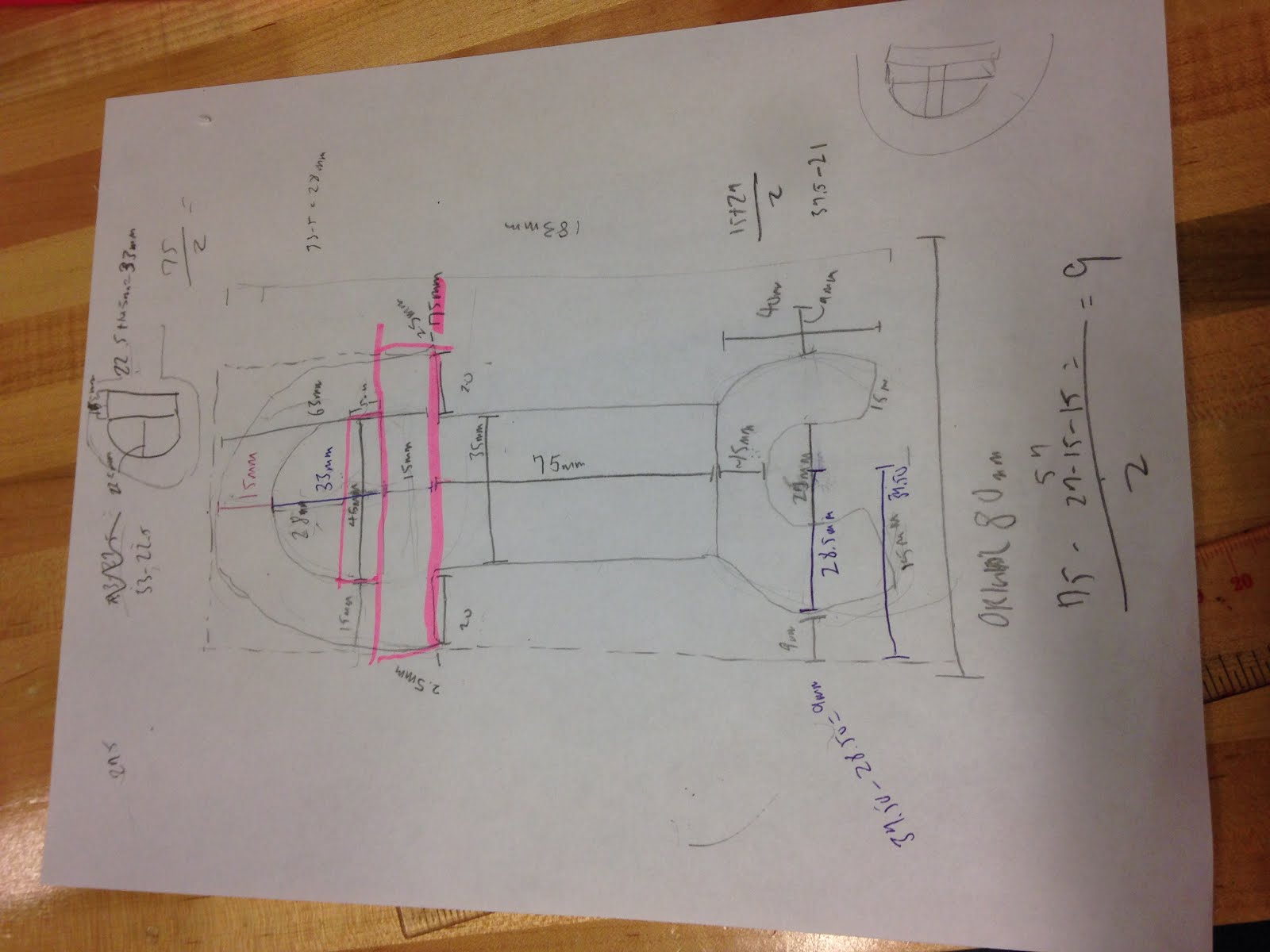
So using simple cantilever physics, we calculated that the bottle-opener would break. However, this depends purely on where the force is applied. We found that holding your hand close to the bottle, placing your thumb on top of the bottle cap, and lifting with the outside side of your hand (bringing the pinky side up towards the sky!) would result in -- in fact -- not a broken bottle-opener but an open bottle!

Engineering Analysis (justification for modifications):

  1. adjust the inner circle (on the claw side) so that it is wide enough to slide onto the bottle cap.
  2. adjust the inner circle diameter so that if it needs to be cut multiple times in the laser cutter, it will not significantly affect the fit of the claw around the neck
Cantilever equations:

δ= F(L)^3
       3EI

I= b(h)^3
       12

Immutable:
F (approximately) = 69N
E(Young's Modulus) = 2.6 GPa

Mutable:
L (approx, depending on how close your hand is to the bottle neck, closer is preferable) = 22.25mm
b = 13.5(pi)
h = 3/16'' or about 4.7625 mm

δ(approx)= 1.03mm

σmax = 13.1681 MPa (a factor of 5 below the yield strength!)


Step 7: Design/print the second prototype.


Note: Our added aesthetic in color decoration using Sharpie was not every long lasting because acetal is very low friction, and the design is likely to wear off soon.

Secondary Note: On testing day, opening the bottle soda was actually harder than the model bottles we used (that we had re-sealed ourselves). Perhaps it was the pressure of everyone watching us, perhaps it was that there is a significant difference in the tightness of the seal of a pressurized soda bottle and an empty one.


Reflection:
Although this first project was, at times, daunting and frustrating, I found it was also very rewarding/empowering. To go from something so simple -- a drawing on a page -- to a real life fleshed out tool is absolutely amazing. Each of the steps in the process of making a product are key and important to helping trouble-shoot in the future (aka when your first model doesn't work out.) In addition, calculating the maximum deflection and the yield strength of the model, even if they aren't exact, are great tools to help improve a model.

Notes about this product (and making others) for the future:

  • is acetal the best choice of material?
  • is there a way to use a thicker material (1/4'') without compromising the fit on the bottle neck?
  • is there a more effective (or precise) way to cut acetal without using the laser cutter? (mass production of this tool would not be efficient if we have to trace the cut 2-4 times)
Skills learned/worked-on:
  • brainstorming
  • 3D modelling in SolidWorks
  • basic cantilever calculations